GigaBaudics
Features
- High-speed TTL programming
- 50 ohm matched I/O
- DC to 3 GHz bandwidth
- Passive switched-line delays
- 10 Bit (1024 step) range
- Custom step size (5, 10 or 20 ps)
- Time or phase shifting
- Precise repeatability
PRODUCT DESCRIPTION .... SPECIFICATIONS .... PROGRAMMING .... CIRCUIT DIAGRAM .... TRANSFER CHARACTERISTICS .... PRICING AND AVAILABILITY ... HOME PAGE
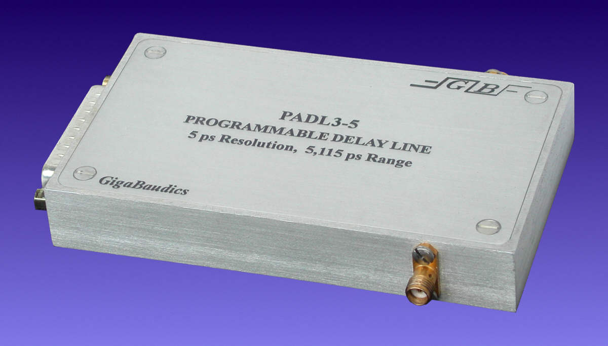
The PADL3 is a single channel programmable delay line instrument designed for adjusting the time delay or phase of radio, microwave or even digital signals with bandwidths from DC to 3 GHz.
This instrument can be an attractive alternative to either the manually operated, hand-cranked, line stretchers which are very time consuming when delays have to be changed frequently or the servo-controlled line stretchers which are expensive and wear out quickly. It also has the advantage of lower mismatch, higher bandwidth and higher range than delay lines that use lumped or distributed varactor elements.
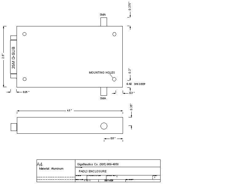
The PADL3 programmable delay lines employ all GaAs passive microwave switched-line techniques. Lines are switched in a series configuration so that each delay occurs additively with any other switched-in delay. The signal is DC coupled therefore has no lower band limit. Since no active elements are used, input power of as high as 20 dBm may be used and still yield less than 1 dB compression. The delay lines I/O provide a good match of 50 ohms relative to ground yielding a VSWR of less than 1.3 from DC to 3 GHz and less than 1.5 to 3 GHz. This enhances its usefulness in applications where the signal source and termination are not well matched. Poorly matched I/O terminations can generate reflections, which may result in delay-shift aberrations when the incident signal and the reflected signal are coincident. SMA jacks connect inputs and outputs, while a standard 25 pin D-type connector connects data and control signals. This instrument is provided in a low profile rugged aluminum housing and requires a single, low power, 5V supply making this instrument very easy to use.
Delays are controlled precisely in standard step sizes of 5, 10 or 20 picoseconds or in any custom step size within this range. The delays are 10 bit programmable giving a total of 210=1024 steps. Therefore the PADL3-5, -10 and -20 have a delay range of 5115, 10230 and 20460 ps respectively. When this device is used as a programmable narrow band phase shifter the phase shifts are proportional to the frequency. The equivalent phase shift for a delay, is 0.36 deg./ps GHz or 2.78 ps = 1 deg/GHz. Fast TTL control logic is used in this instrument for applications requiring rapid delay-state changes delay-state changes up to 30 MHz.. The PADL3 is calibrated to maintain a high degree of delay accuracy over a wide range of frequencies. The delay accuracy is better than 1 LSB (20 ps for step sizes above 20 ps). This device has high delay monotonicity. The accuracy maintained between consecutive delays is 1/2 LSB (1 LSB for 5 ps step sizes). The differential loss between delay elements is balanced so that the total loss does not vary widely between delay states.
The delay line consists of passive GaAs microwave transfer switches. The switch network series resistance losses are matched with shunt resistance to ground for improved wide-band matching.
The diagram above shows the PADL3-5 typical transfer characteristics. The differential loss between arbitrary delay states is less than +0.5 dB DC to 2 GHz, +1.0 dB from 2 to 3 GHz and +1.5 dB from 3 to 4 GHz.
Each of the 10 programming bits represents a binary number corresponding to a delay state equal to the binary number times the step size. This gives 210 = 1024 possible combinations and a delay range equal to 1024 x (step size). The control word may be latched by using the "LE" latch line (see function diagram and pin-out diagram). The control word need not be latched if the user wishes to operate the latch transparently. Simply keep the latch line high and the delay state will follow the applied data. Delay-state on/off and off/on time is about 30 ns (with a 9 ns propagation delay).
|
25 pin, male, D-type subminiature connector |
The PADL3 uses a single 5V supply. The current requirement is about 50 mA but may increase up to 200 mA for rapid programming rates. Power dissipation is less than 1 watt. Internal supply voltages are regulated to eliminate supply noise coupling to the signal path. All internal voltages are generated from the single 5V supply, thereby simplifying power-up.
Price: PADL3-5; $3100, PADL3-10; $3295 , PADL3-20; $3500 ____ Price and specifications subject to change without notice. PADL3.pdf
Please use e-mail for any correspondences, either technical or administrative, at address postman@gigabaudics.com
GigaBaudics 5266 Hollister Ave. Ste 221 ● Goleta, CA 93111 ● (805) 687-5934